Background
- - To compare distribution equipment ratings to the results of the Demand Load Study module.
- - To compare distribution equipment ratings to the results of the Load Flow Study module.
- - To compare distribution equipment ratings to the results of the Short Circuit Study module. As long as available fault duty X/R ratios are at or below rated equipment X/R ratios the Short Circuit Study module results will match Equipment Evaluation Study module results.
- - To convert fault duties to the equipment X/R ratio base if the available fault duty X/R ratio is greater than the equipment rated X/R ratio. In this case the Short Circuit Study module results will not match the Equipment Evaluation Study module results.
What is the purpose of a Demand Load Study?
- - To calculate the connected, demand and design loads throughout the distribution system.
- - The results can be used to determine or validate feeder and transformer ratings.
Are electrical engineers required to perform a demand load study?
- - No, however it is good engineering practice.
What is the purpose of a Load Flow Study?
- - To calculate bus voltage levels to compare to equipment ratings.
- - To calculate branch current flows to compare to equipment ratings.
Are electrical engineers required to perform a load flow study?
- - Yes, per NEC Articles 210.19 for Branch Circuits and 215.2 for Feeders. Both articles specify voltage drop limits.
- - NRC requires load flow studies to verify system performance.
What is the purpose of a Short Circuit Study?
- - To calculate maximum available symmetrical fault duties to compare to LV equipment short circuit ratings, and MV/HV equipment interrupting ratings.
- - To calculate maximum available peak fault duties to compare to LV equipment unpublished peak ratings, and MV/HV equipment closing and latching ratings.
Are electrical engineers required to perform a short circuit study?
- - Yes, per NEC Article 110.9: "Equipment intended to interrupt current at faults levels shall have an interrupting rating sufficient for the nominal circuit voltage and current that is available at the line terminals of the equipment."
What are good references for engineers performing load flow and short circuit studies?
- - A Practical Guide to Short-Circuit Calculations, Conrad St. Pierre, to order go to www.epc-website.com.
- - IEEE Std. 141-1993, IEEE Recommended Practice for Electric Power Distribution for Industrial Plants (IEEE Red Book).
- - IEEE Std. 399-1997, IEEE Recommended Practice for Industrial and Commercial Power Systems Analysis (IEEE Brown Book).Example 1
Example 1
Open the existing Dodge City Plant project. Then open the 000 Site One Line drawing.
- - This project has over 900 buses and 4200 components.
- - There are 77 single line dagrams, not including the small single lines printed on the TCCs.
- - There are over 500 TCCs.
Please perform the following tasks as quickly as possible. Remember in the real world you don't have unlimited time to study a problem.
Step 1 - Run a Demand Load, Load Flow and Short Circuit Study.
Step 2 - Review each report and tell me the status of all equipment on the electrical distribution system.
Step 3 - Repeat step 2 using the Equipment Evaluation Module.
I know this is a large system. In my career I worked on 3 projects over 900 buses, about 10-15 projects in the 100-500 bus range, and I've lost count of the smaller projects. In each case, when I've run demand load, load flow and/or short circuit studies I've had to go back and manually compare the results to the equipment ratings.
What do I mean be by manually compare?
In the old days I've had to pull the data from the output reports or data blocks in order to develop summary tables in my report. That was a time consuming task, prone to errors! The Equipment Evaluation Module automates this task. If we understand this module we can greatly improve our efficiency and analysis skills.
If this little exercise does not convince you to use the Equipment Evaluation module, nothing will!
Example 2
Create a new project in PTW consisting of the existing distribution system shown in figure 1.
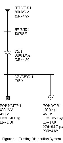
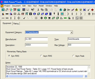
Select the LV Switchboard ratings required for the application.
- Voltage – Standard LV switchboards are designed to be installed on distribution systems rated up to 600V. However, this is not the rated voltage of the switchboard. The rating is set at the nominal voltage of the distribution system it is installed on.
V = 480V
Current – The continuous current rating of the switchboard is selected by the design engineer. There is no standard sizing practice used throughout the industry. In this case we will base our switchboard ampacity rating on the maximum current rating of the source transformer.
I = 2300kVA / (√3 0.48kV) = 2766 A
Ratings in this range include 2500 and 3000 amps. Select 3000A.
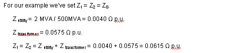
Short Circuit Rating – The short circuit rating must be greater than the available fault duty. The available fault duty at 480V consists of contribution from the utility through the transformer
SC utility = MVA transformer / ( MVA transformer / MVA utility + Z transformer ) SC utility = 2 MVA / ( 2 MVA / 500 MVA + 0.0575 ) = 32.52 MVA
and the contribution from the motors.
Z new = Z old (V old / V new) 2 = 0.17 (460 V / 480 V) 2 = 0.156 Ω p.u.
MVA motor = 0.746 HP / ( pf * h * 1000 )
MVA motor = 0.746 1000 HP / ( 0.85 * 0.92 * 1000 ) = 0.954 MVA
SC motor = MVA motor / Z new = 0.954 MVA / 0.156 Ω p.u. = 6.12 MVA
The total short circuit capacity available is
SC total = SC utility + SC utility = 32.52 + 6.12 = 38.64 MVA
SC total = 38.64 MVA / (√3 * 0.48 kV ) = 46.48 kA
Ratings in this range include 42 kA and 50 kA. Select 50 kA.
Since this is a new project and we do not know the manufacture select a UL rated LV Switchboard.
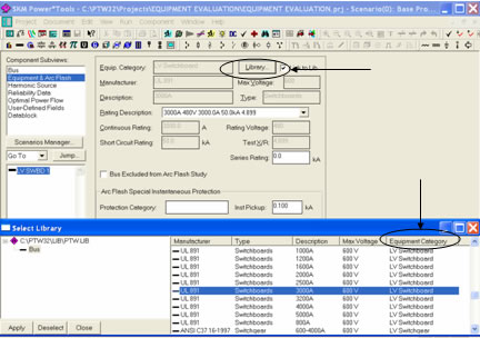
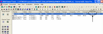
Next run an Equipment Evaluation.
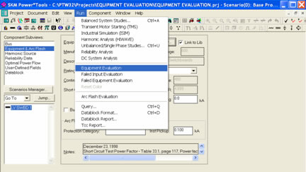
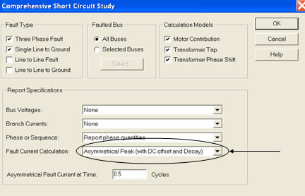
Then click on the Run Study button, check the appropriate boxes, and click OK.
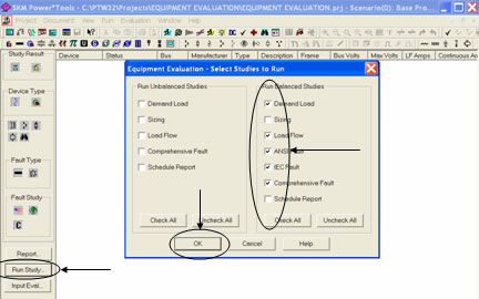
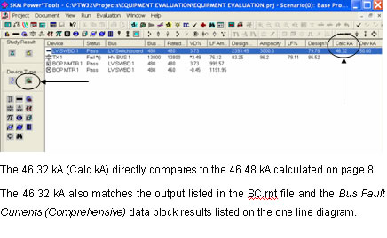
After the calculations are completed close the Study Messages window, click on the non-protective devices button and view the Calc kA field.
Distribution Equipment X/R ratios
The ANSI, IEEE and UL standards provide manufacturers with basic design and performance requirements. One aspect is the ability to withstand and interrupt fault current. Table 1 lists applicable standards and short circuit test parameters for selected types of electrical distribution equipment.
Table 1 – Distribution Equipment Short Circuit Test Data
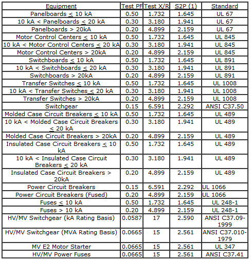
Notes: The symmetrical-to-peak (S2P) factor is calculated using equation 2. The purpose of the S2P factor is to calculate the unpublished peak rating the equipment would carry according to the short circuit test procedures outlined in the applicable equipment standard. The unpublished peak rating would be calculated using equation 3.
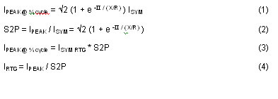
Equations
The following equations were used to derive and calculate the symmetrical-to-peak (S2P) factor.
Example 3
Calculate the unpublished peak rating of the LV switchboard of example 2 using equation 1.

Example 4
Verify the S2P factor listed in Table 1 for switchboards with SC ratings > 20kA. Use the switchboard of example 2 and equation 4.

Example 5
Repeat Example 2 for the system shown in figure 2. However, in this case consider currently available high efficiency motors and transformers.
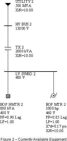
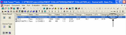
Re-run the studies and display the result.
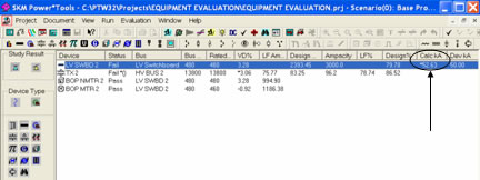
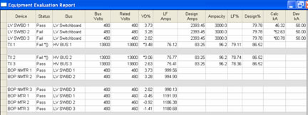
The fault duty has now changed in the Calc kA field from 46.32 kA in Example 2 to 52.63 kA.
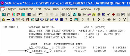
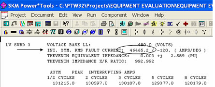
Check the results listed in the SC.rpt file and the results displayed using the Bus Fault Currents (Comprehensive) data block.
Both list 46.4 kA
Why is there a discrepancy?
If the fault duty X/R ratio is higher than the equipment rated X/R ratio the equipment evaluation will convert the fault duties to the equipment X/R ratio base. In these cases the Short Circuit Study results will not match Equipment Evaluation results.
Actually the Equipment Evaluation Calc kA column can be thought of as the Required Rating column.
How is this Required Rating determined?
Calculate the peak duty available at the LV switchboard using equation 1. Verify the results in PTW.

To verify this result in PTW select Run, then Balanced System Studies. Next click the Setup button and select AsymmetricalPeak (with DC offset and Decay) for the Fault Current Calculation. Finally click OK to close the window and Run to update the duties.
The 113.74 kA calculated on page 15 directly compares to the 113.62 kA listed in the SC.rpt file.
If the fault duty X/R ratio exceeds the equipment rated X/R ratio the peak duty represents the limiting parameter for the application, and the required minimum rating for the application can be calculated using equation 4.

This rating can be directly compared to the Equipment Evaluation results listed in the Calc kAcolumn.
Another way of looking at this application is:
A 52.68 kA (X/R=4.899) LV switchboard is required for application on a 480V distribution system with 46.48 kA (X/R=10) available. This application will assure that the rated symmetrical and peak currents will be equal to or greater than the available symmetrical and peak duties.
Please note if the electrical engineer did not use the Equipment Evaluation module he would have to do these calculations by hand.
Example 6
Repeat Example 5 for the system shown in figure 3. In this case consider superconducting motors and transformers, i.e., – no I2R losses.
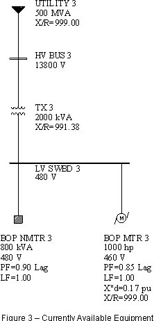
The symmetrical duty is the same as in examples 2 and 5.

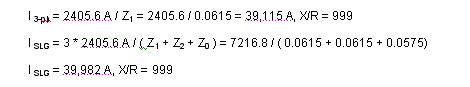
The fault duty X/R ratio is 999, and the peak duty using equation 1.

The required rating for the application can be calculated using equation 4.

Validate the results using PTW.
The Equipment Evaluation results indicate 60.78 kA.
The SC.rpt file results do not agree with the Equipment Evaluation results, as expected.
Example 7
Repeat Example 6 with the induction motor contribution out of service.
In this case the fault duty at the LV switchboard is limited to the contribution from the utility only, see page 8.

Adjusting for the X/R ratio

The required rating for the application can be calculated using equation 4.

This does not agree with the results of the Equipment Evaluation (52.30 kA). Why?
The reason for this discrepancy is that the Equipment Evaluation Study module will look at both the 3-phase and single-line-to-ground fault and use the worst case. When we turned the motor contribution off, the single-line-to-ground fault became the worst case at the LV switchboard bus. Let's verify.
The Thévenin equivalent zero sequence impedance at the LV switchboard bus equals the transformer impedance because of the Δ-YG connection, see Figure 4.

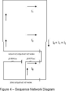
In this case
Adjusting for the X/R ratio

The required rating for the application can be calculated using equation 4.

This compares directly to the 52.30 kA of the Equipment Evaluation screen on page 19.

Example 8
Put all components in service from sample problems 2, 5 and 6. Then add the following components.
- - Square D VR, 1200A, 500MVA, 15kV breaker to the line-side of each transformer.
- - Westinghouse CO-9 relay to the line-side of each transformer
- - GE, TP & THP, MVT RMS-9 with LSI, 2500-3000A Sensors set at 3000A to the load-side of each transformer
- Re-run Equipment Evaluation
- Re-run studies
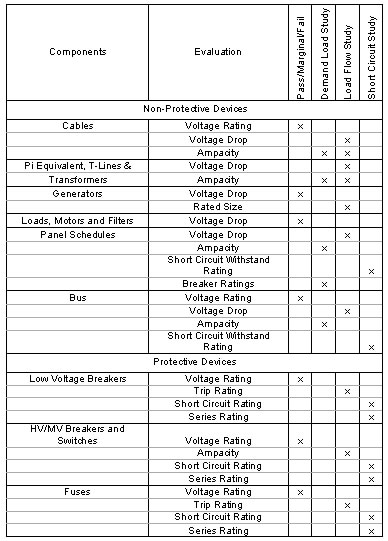
Equipment Evaluation Overview
Table 2 – Equipment Evaluation Summary Table
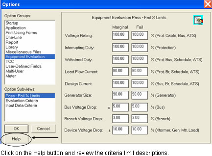
EquipmentEvaluationCriteriaPass – Fail % Limits
Select Project from the drop down menu. Next select Options. Finally select Equipment Evaluation. The default criteria table is listed below. It may be customized for each project.
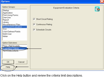
Equipment Evaluation Study Criteria
Select Evaluation Criteria. Users may customize what studies to consider in their evaluation.
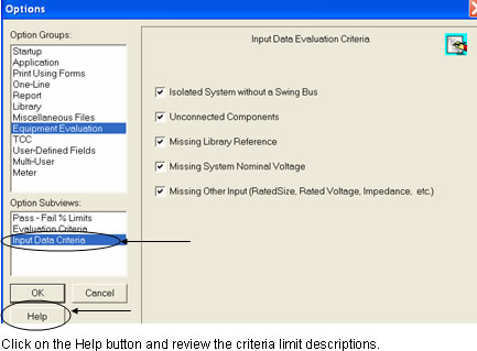
Input Data Criteria
Select Input Data Criteria. Users may customize what input data to consider in their evaluation.
Click on the Help icon and place the cursor on the lower left of side of the screen and click. Review the study selections and options available.
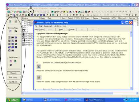
- - Study Options
- - Device Type
- - Component
- - Query
- - Fault Study
- - Report
- - Run Study
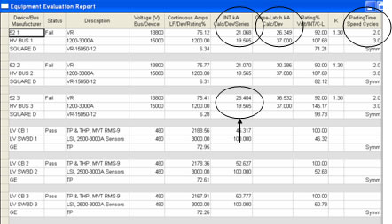
Non-Protective Device Output Reports
Put all devices in service and run an Equipment Evaluation and display the report
Protective Device Output Reports
Note relays are not included in the Equipment Evaluation.
Example 8
Why do the HV breakers fail?
Review the breaker rating table on the following below.
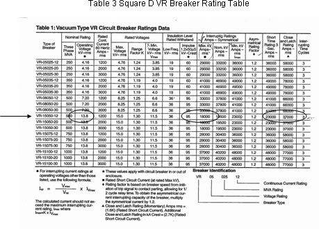
We selected a Square D, VR-15050-12, 3-cycle breaker rated 15kV, 1200A, 18kA RMS symmetrical interrupting, 37kA RMS asymmetrical Close & Latch. We must first adjust the interrupting rating for the operating voltage per the note at the bottom of Table 3.

This matches the Equipment Evaluation printout.
The Close & Latch (Momentary) rating is not adjusted. It is read directly from the Square D table. It also matches the Equipment Evaluation printout.

Next we calculate the available fault duty at 13.8 kV. This consists of fault current from the utility and the motors. The contribution from the utility

and the contribution from the motors.

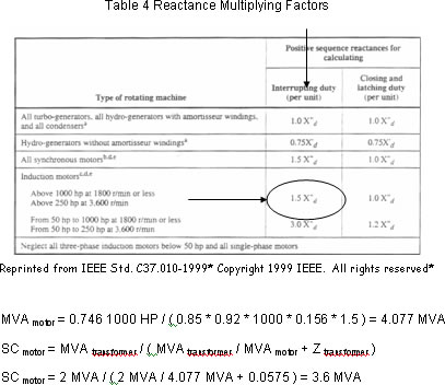
The Reactance Multiplying Factor (RMF) is read from table 4 (?)
Table 4 Reactance Multiplying Factors
The total short circuit capacity available is
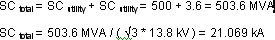
This current is the same magnitude with an X/R ratio equal to 4.899 (HV Bus 1), 10 (HV Bus 2) or 999 (HV Bus 3). We must now adjust for the X/R ratio. The test X/R ratio for this type of equipment is 15, see Table 1. Therefore, we do not adjust for breakers 52-1 or 52-2.
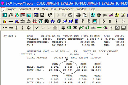
However we must adjust for breaker 52-3. From Table 6 for an X/R ratio of 999 we can read for a 3-cycle breaker a MF of 1.35. Note, the table only goes up to an X/R of 130.
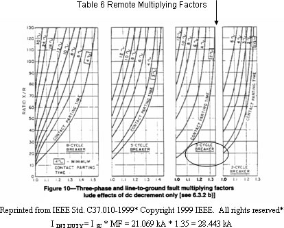
This matches the results of the Equipment Evaluation and the SC.rpt file.
Example 9
A co-worker has brought you the following single line diagram. The client he is working for is coming into the office for a review meeting. He would like you to quickly pop his proposed system into PTW and tell him what short circuit ratings are required for the SWBD and 2 panels.
- - There is no charge number for this assignment.
- - Make assumptions for missing data!
- - His last request is that since there are so many unknowns he does not want to be within 80% of the equipment short circuit rating.
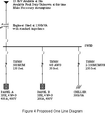
Based on the given system information, assumptions and design criteria the following ratings are required.
SWBD = 50kA, Panel A = 22kA and Panel B = 35kA
Recommendations
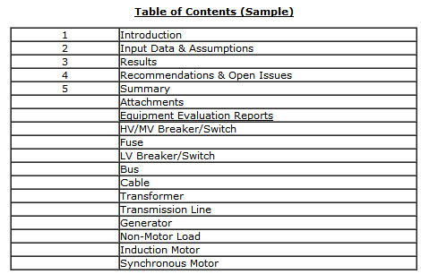
Take full advantage of the Equipment Evaluation Study module. Here is a sample table of contents from the last study I worked on. It was a large system. Sections 1-5 were brief, less than 20 pages total. I attached all the equipment evaluation reports by component type and status. This approach has 2 advantages.
- - Easy for the client to review
- - Easy for the next person to update the report
Final Comments
- - Link Components to Libraries – take advantage of the extensive database
- - Let software compare the results of the calculations to the selected equipment ratings
- - Let the software adjust for the X/R ratio
- - Let the software determine the worst case fault current available