How shifting of protective devices works in PTW (CAPTOR):
This FAQ will show how to shift protective devices in CAPTOR and will go over a sample shifting calculation.
During fault conditions you could have contributions for multiple locations with several protective devices operating to clear that fault contribution. Usually each protective device will see a different amount of fault current and trip at a different time. When plotting the time-current curves (TCCs) of these protective devices for a fault at a predetermined location, the trip curves are plotted based on real current.
To show accurate coordination of these protective devices for a given fault condition (assuming some of the devices see a different amount of current) you will have to shift the curves on the TCC. To do this you will need to either select a reference device that all other devices will shift around or base your shifting on the total current. We will explain this in more detail below:
Once you determine a location that you would like to use this feature:
- 1. Plot the respective devices in the TCC.
- 2. Right-click on the TCC and select 'TCC Settings'
- 3. Go to the Fault Current tab. (See Below)
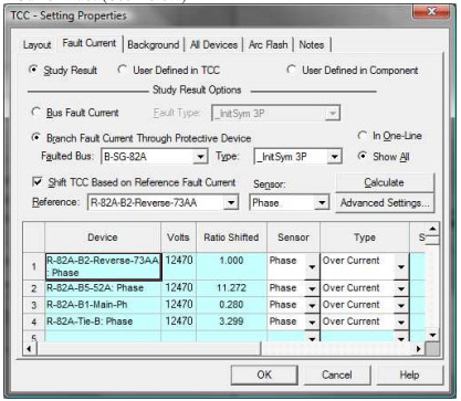
- 4. Select 'Branch Fault Current Through Protective Device'
- 5. Select the faulted location/bus and select the type of current you want to use.
- a. Ex: 3P, SLG, ANSI, InitSym, etc..
- 6. Then check on the 'Shift TCC Based on Reference Fault Current' box.
- 7. Choose your reference device or use the total fault current.
- a. A reference device will shift all devices based on that one
- b. The total fault current will shift all the devices based on the total current.
- 8. Select whether you want to sense Phase or Neutral current.
- 9. Then click on 'Calculate'.
Note: The Reference Voltage of the TCC will be set to the system nominal voltage of the reference device automatically.
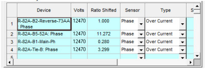
PTW will calculate the 'Ratio Shifted' or the number of multiples of current that the device will be shifted. This is shown in the spreadsheet below:
Once the device in the TCC has been shifted, you will be able to show a user-defined fault current line for all protective devices in the TCC. This will show the actual coordination for a fault at that location.
An Example of this is shown below.
Example:
One-line showing the fault location (B-SG-82A) and the fault current direction:
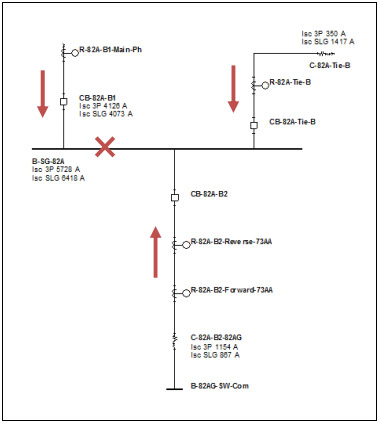
- This one-line shows the bus fault current and the branch current flowing into the bus.
Protective devices plotted in the TCC (without shifting):
The fault current line is only shown for the reference device (R-82A-B1-Main-Ph). The other two relays are seeing a different amount of current shown below:
| Relay 'R-82A-B1-Main-Ph' | Sees 4,126A |
| Relay 'R-82A-B2-Reverse-73AA' | Sees 1,154A |
| Relay 'R-82A-Tie-B' | Sees 350A |
Using 'R-82A-B1-Main-Ph' as the reference device means that all devices will be shifted based on the amount of current this device sees. Therefore:
| Relay 'R-82A-B1-Main-Ph' | Ratio Shifted = 4,126/4,126 = 1 (no shift) |
| Relay 'R-82A-B2-Reverse-73AA' | Ratio Shifted = 4,126/1,154 = 3.575 |
| Relay 'R-82A-Tie-B' | Ratio Shifted = 4,126/350 = 11.794 |
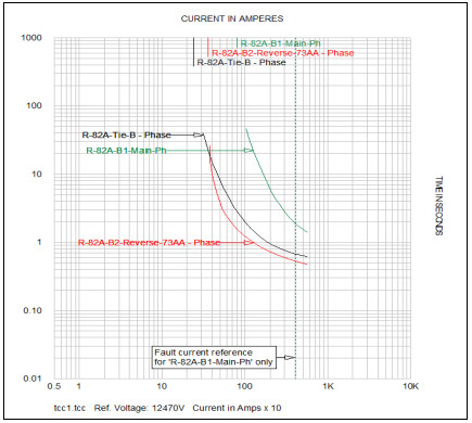
Protective devices plotted in the TCC (with shifting):
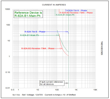
Previously the user-defined fault current line was only good for one device on the TCC (R-82A-B1-Main-Ph). Now the line applies to all devices, so you now get an accurate idea as to what happens as time increases and the coordination distances between devices.
From this TCC you will notice that:
| Relay 'R-82A-B2-Reverse-73AA' | Operates in: | 1.075s |
| Relay 'R-82A-B1-Main-Ph' | Operates in: | 1.86s |
| Relay 'R-82A-Tie-B' | Operates in: | 27.3s |