How do I model an Uninterruptable Power Supply in Power* Tools?
For AC studies in Power*Tools, the UPS model can be selected by clicking on UPS component from the component toolbar.

The UPS will be feeding an AC load and its active power is equal to that of the connected load when considering the UPS efficiency. The UPS input reactive power depends on the load power factor.
Modes of Operations:
In PTW, the UPS can work in different modes of operation. The different modes of operation can be chosen from the drop-down list.
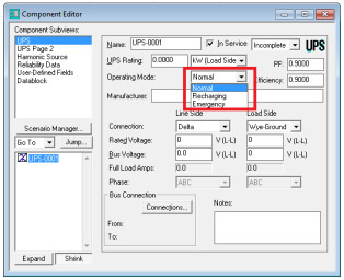
Normal
This mode resembles the normal operation of the UPS. In this mode, the UPS receives power from the line side, and supplies power to the load side, while providing a float charge to the internal battery.
In the following example, a UPS is feeding a 100 kW load with PF= 0.8. The UPS power factor and the UPS efficiency is 0.9.
The following figure shows how the voltages and currents are related to each other on both sides of the UPS. PTW assumes that the input power factor of the UPS is equal to that of the load. The efficiency of the UPS is also considered.
The load demands 100 kW and 75 kVAR. Considering the fact that the UPS efficiency is 0.9, the input active power will be 111.1 kW. The input power factor is 0.8; therefore, the input kVAR is 83.33.
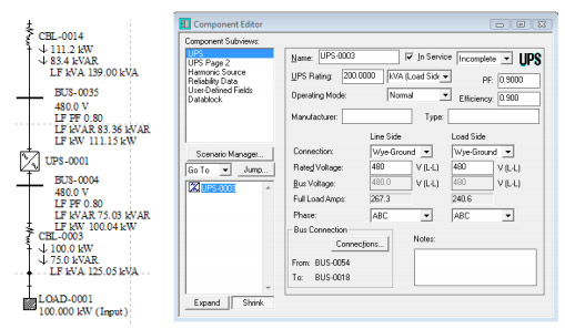
In the load flow study, the UPS will not affect the input power factor of the load. However, it will change the power flow due to its efficiency. There will be some losses inside the UPS due to its internal resistance. This means that the input active and reactive powers to the UPS are different from those of the load.
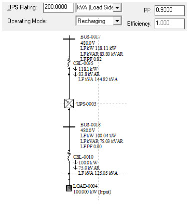
Recharging
In the recharging mode, the UPS takes power from the line side, charges the battery, and supplies power to the load side. The following input field will determine the rate of recharging.
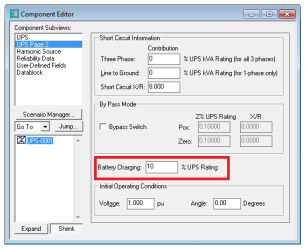
Battery charging = 0% UPS rating
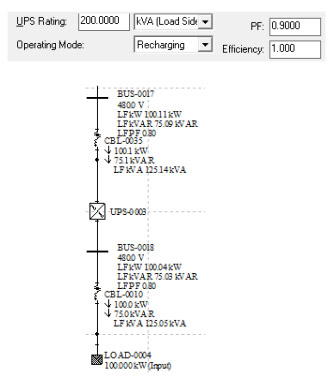
Battery Charging = 10% UPS rating
Emergency
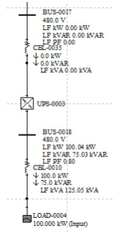
In the emergency mode, the UPS takes power from the battery and supplies it to the load side. The following figure shows the UPS in the emergency mode.

Short Circuit Study
In a short circuit study, the UPS contribution to the fault will be determined by the values entered in Short Circuit Information fields on the "UPS page 2" subview menu.
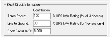
The first two values will be used to calculate the equivalent impedance of the UPS and the third value will be the ratio of the X to R in the impedance.
If the bypass checkbox is checked, the UPS will be considered as a simple impedance. The value of this impedance can be entered in the following fields:

Note: The mode of operation has no effect on the contribution current.
Harmonic Study
In a harmonic study, the UPS can be a harmonic source depending on the model, which is selected from the harmonic library.