How do I model a VFD in V6.5?
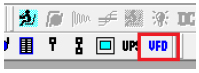
For AC studies in Power*Tools, the VFD model can be selected by clicking on VFD component from the component toolbar.
This component will be feeding an AC load. The load that VFD feeds will determine the input active power of it. In other words, the input active power is equal to the output active power.
In the following example a VFD is feeding a 300 kW motor.
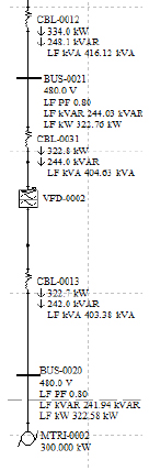
The PF into the VFD will have the same PF as the load it feeds, as long as the input line reactor is zero. If a value is entered for the VFD line reactor, the VFD input reactive power will increase and consequently, the input power factor will change.
The above figure demonstrates how the input and output voltages and powers are related to each other. For the above VFD, the line reactor is 1%. Therefore, a slight difference exists between the input and the output reactive power.
The VFD will also affect the short circuit study results based on the contribution values from the "VFD page 2" section. If the by-pass switch is checked, PTW will by-pass the VFD and only the impedance of the cable will be considered.
Load Flow Study
In the load flow study, the VFD will not affect the power factor of the load, as long as there is no line reactor. The higher the value of the line reactor, the more reactive power the VFD consumes. This changes the VFD input power factor. The input active power of the VFD is equal to that of the load it feeds.
Short Circuit Study
In the short circuit study, the VFD contribution to the fault will be determined by the values entered in the "VFD page 2" section.
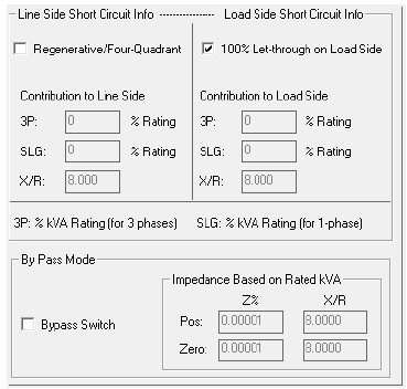
The "Regenerative/Four-Quadrant" check box is for VFDs that can work in regenerative mode. If this option is checked, the VFD will supply short circuit contribution to the upstream bus. The contribution amount depends on the value entered in the "3P", and "SLG" boxes.
If the "100% Let-through on Load Side" box is checked, PTW will allow the VFD to pass the entire short-circuit current to the downstream bus. If this is unchecked, "3P" and "SLG" input fields must be completed. This will determine the amount of the VFD contribution to the downstream fault.
If the "Bypass" switch is checked, the VFD will be shorted. PTW will only consider the impedance of the cable for the VFD. These impedances are to be entered by the user.
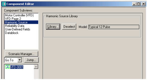
Harmonic Study
In a harmonic study, the VFD can be a harmonic source depending on the model, which is selected from the harmonic library. The harmonic source can be assigned in the "Harmonic Source" sub view of the VFD.