How to use Selective Coordination in PTW:
NEC 2005 definition of Coordination (Selective): "Localization of an overcurrent condition to restrict outages to the circuit or equipment affected, accomplished by the choice of overcurrent protective devices and their rating or settings."
The selective coordination feature can be accessed and used in one-line drawings, TCC drawings (Time-Current Curve), and in the Component Editor.
You have the option to start from the upstream device to find tested selectively coordinated combinations for the downstream device. You may also start with the downstream device to find tested selectively coordinated combinations upstream.
Once a reference device is selected, you can follow one of the three methods below to find the other device.
On the One-line:
- Step 1: Determine which device is your reference device (downstream or upstream). Once you have a reference device you will go to the other device (either up or downstream) you want to find a pair for.
- Step 2: Right-click on it and select 'Selective Coordination'. (See below)
The screen below will appear: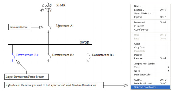
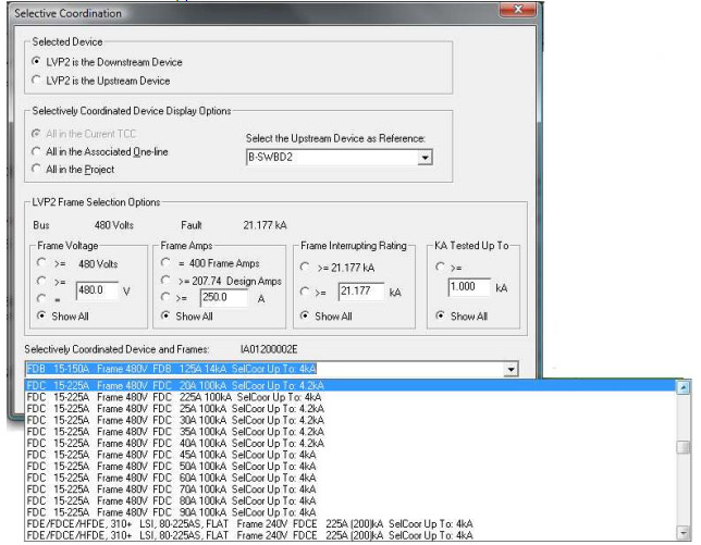
Selected Device: In this section you will decide whether the selected/specified device is either the upstream or downstream device.
Selectively Coordinated Device Display Options: If you choose the upstream device in the previous option, you will choose the downstream in this option (and vice versa). Devices in the dropdown menu depend on the option selected on the left.
Frame Selection Options:
- Frame Voltage: The frame voltage of the reference device will be used to filter the search results. A user-defined and a Show All option are also available.
- Frame Amps: The frame amps of the reference device will be used to filter the search results. A user-defined, design amps (FLAs), and a Show All option are also available.
- Frame interrupting rating: The interrupting rating of the reference device will be used to filter the search results. A user-defined and a Show All option are also available.
- kA Tested Up To: Selective level of current required for your application.
Selectively Coordinated Device and Frames: This list will display tested selectively coordinated combinations based on the options selected above. Devices will be listed in alphabetical order and will include the device name, ampere range, frame voltage, frame name, continuous rating, interrupting rating, and the level they are selectively coordinated up to.
You have two buttons to choose from 'Search All' and 'Search by Criteria'.
Search All: Use this option when searching for the first time.
Search by Criteria: Use this option when changing the filter criteria after initially searching. This will yield faster results.
* From the list, you can choose a device that best fits your needs. The last column will indicate the maximum level of selective coordination you will achieve by selecting that device. Once you select the device and press OK, the software will automatically associate that device and rating with the upstream or downstream device that you selected in the selective coordination window. It will also take into account the manufacturers assumptions from the tables.
In the TCC:
Step 1: Determine a reference device.
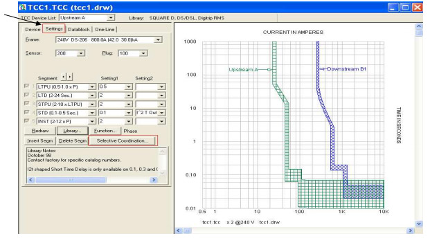
Step 2: Select the device you want to find a combination for and click on the Selective Coordination button. The main Selective Coordination menu will appear (page 2).
In the Component Editor:
Step 1: Determine a reference device.
Step 2: Select the device where a combination is desired and click on the Selective Coordination button. The main Selective Coordination menu will appear (page 2).
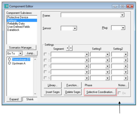
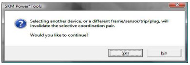
Once two devices are selectively coordinated with each other, the 'On' box will be checked to indicate that this device is selective with another one. If there is an attempt to change the library device while this box is checked, the software will display the following warning dialog:
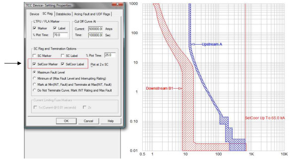
Coordination marker and label: The coordination marker is a line that can be added to the TCC to show the maximum level of selective coordination between a pair. The label is a text block showing the actual value.
Step 1: Select the downstream device in the TCC
Step 2: Right-click and select 'Selected Device Settings'. Go to the SC Flag tab.
Step 3: Here you can select to show the SelCoor Marker and/or SelCoor Label
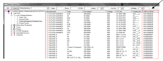
Library filter: A column called SelCoor Notes has been added so you can easily determine which devices in the library have selective coordination information. The manufacturer's table number will reside in this column.;