Overcurrent Coordination Basics Cables |
||
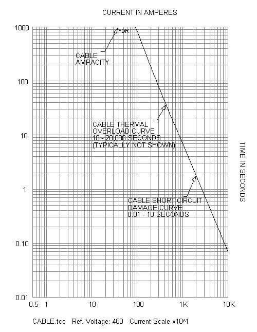
| This technical guide contains a suggested method for the overcurrent protection. The information is presented for review, approval, interpretation and application by a registered professional engineer only. SKM disclaims any responsibility and liability resulting from the use and interpretation of this technical guide. Reproduction of this material is permitted provided proper acknowledgement is given to SKM Systems Analysis Inc. Purpose The purpose of this guide is to provide a basic overcurrent protection philosophy for insulated power cables. Cable Overcurrent Protection Time current curve (TCC) landmarks (figure 1) |
||
| • Ampacity – located in the upper decade • Thermal Overload Curve – located in the upper 2 decades, typically not shown • Short Circuit Damage Curve – located in the bottom 3 decades |
||
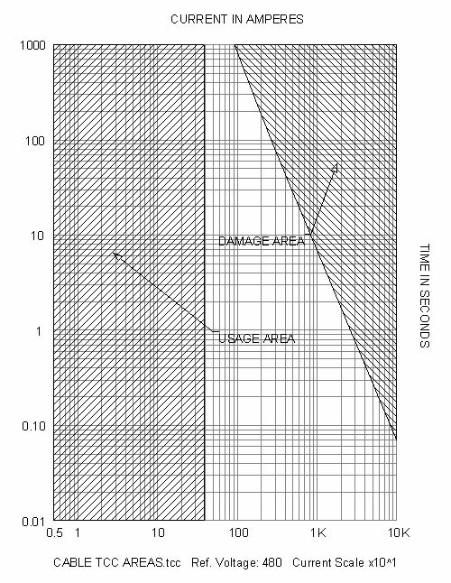
| TCC areas (figure 2) | ||
| • Usage Area – located at and to the left of the cable ampacity rating • Damage Area – located at and to the right of the overload and damage curves |
||
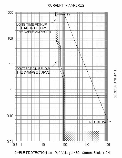
| Suggested overcurrent protection (figure 3) | ||
| • Set long time pickup (LTPU) at or below the ampacity • Set protection above the usage area • Set protection below the thermal overload curve • Set protection below the short circuit damage curve |
||
| Comments | ||
| • If current penetrates the limits of the thermal overload curve, cable insulation life is reduced. • If the maximum thru-fault current penetrates the limits of the short circuit damage curve, insulation damage will occur. The thru-fault current is defined as the maximum current that can flow for a fault at the load-side terminals of the feeder. |
||
 |
||
| Fig. 1 Cable TCC landmarks. | ||
 |
||
| Fig. 2 Cable TCC areas. | ||
 |
||
| Fig. 3 Cable overcurrent protection. | ||
| References | ||
| Other SKM Technical Guides offered at www.skm.com. The latest revision of IEEE Std 242, IEEE Recommended Practice for Protection and Coordination of Industrial and Commercial Power Systems (IEEE Buff Book). |
||
| back to Application guides | ||