Modeling Arc Flash Mitigation Technique Using the SKM Power*Tools for Windows Software Lowell L. Oriel
Arc flash is one of the most dangerous workplace hazards. It could cause serious injuries and fatalities. Furthermore, it could cost companies millions in damage to equipment as well as worker's compensation. An arc flash incident occurs when electric current passes between two conducting metal through ionized air. When this phenomenon happens, a large amount of heat (incident energy) is released that can severely burn human skin and set clothing on fire. Besides the intense heat that could reach up to 5000F, electrical arc flash also produces high-pressure blast with molten metal and shrapnel, as well as deaf dying sounds.
Equations developed by electrical safety standards (IEEE 1584 and NFPA 70E) to calculate the potential incident energy caused by an arcing fault indicates that the faster the arcing fault is cleared, the lower the incident energy. Therefore, one of the best and efficient ways to mitigate arc flash incident energy is to clear the arcing fault as fast as possible.
There are various ways to clear the arcing fault. One way is by simply modifying the existing settings of protective devices. Another way is to apply new technologies that have been developed to clear the arcing fault instantly during an arc flash incident. Finally, another way is by taking advantage of alternative protection schemes such as differential protection and zone interlocking, since these types of schemes clear the fault instantaneously.
The various arc flash mitigation techniques mentioned above will be illustrated and modeled using the SKM Power*Tools for Windows software.
Changing Instantaneous and STPU setting
The easiest way to reduce clearing time of arc fault is by reducing the instantaneous setting or the short time pickup (STPU) setting of a protective device. The following four figures illustrate this. Figure 1 shows a partial single line modeled in SKM software along with its corresponding time current curve (TCC). From the figure, we can see that if the fault happens on the "E SWBD"(Critical Switchboard), the arcing current of 15.95 kA going through, "CSWB MCB" will clear the fault at 0.215 seconds. This will produce a total incident energy of 11.3 cal/cm2.
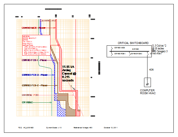
Figure 1
Now, if the instantaneous setting of the "CSWB MCB" device is changed from 20 to 10, as in Figure 2, it will then clear the fault at 0.018 seconds. This will then produce a total reduced incident energy of 1.0 cal/cm2.
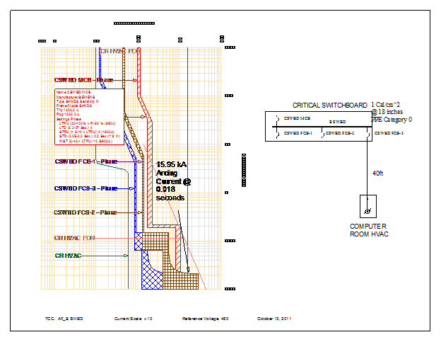
Figure 2
An example of how changing the STPU of a protective device could also reduce the incident energy can be seen in Figure 3 and 4. Figure 3 shows a partial single line modeled in SKM software along with its corresponding time current curve (TCC). From Figure 3, we can see that if the fault happens on bus "MCC#1A", the arcing current of 9.38 kA going through, "52-SUB3A-MCC1A" will clear the fault at 0.24 seconds. This will produce a total incident energy of about 10.4 cal/cm2.
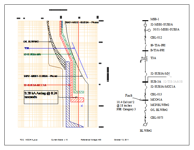
Figure 3
Now, if he STPU setting of the "52-SUB3A-MCC1A" device is reduced from 0.2 to 0.1, as in Figure 4, it will then clear the fault at 0.15 seconds. This will then produce an arc-flash incident energy of 6.7 cal/cm2.
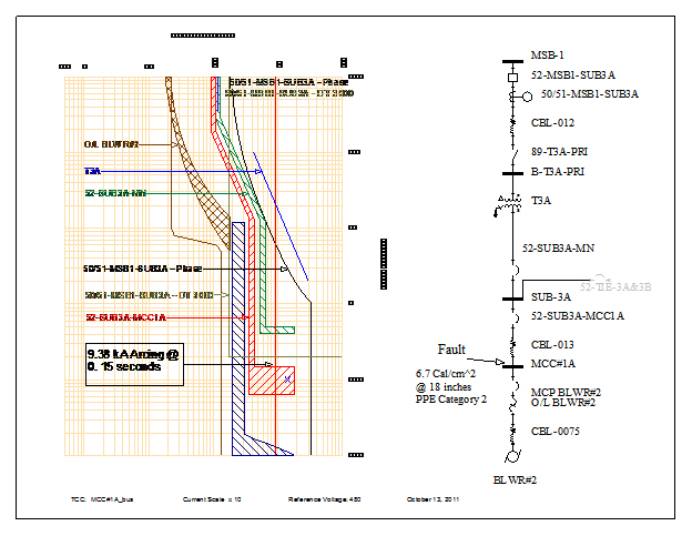
Figure 4
Note that special care must be taken when changing the STPU or the instantaneous settings of protective devices to mitigate arc flash. One should not just haphazardly lower the settings to reduce the tripping time of devices. One must be careful that no overlapping of TCC or mis-coordination is mistakenly achieved on other part of the system when the settings are lowered. Mis-coordination could cause nuisance tripping or even increase the incident energy on the other part of the system.
Maintenance Switch and Multiple Settings Group
Another effective way of lowering the arc-flash incident energy is by temporarily over-riding the breaker's or relay's delay function to trip without intentional delay whenever a fault is detected. This can be achieved by applying maintenance switch or multiple settings group during maintenance mode of operation.
An ARMS (Arc Resistance Maintenance Switch) is device that you can retrofit with certain existing trip unit, such that when the ARMS is switched on, the tripping time of the unit is very fast when a fault is detected. When a person wants to perform maintenance, the maintenance switch is turned on. The breaker's delay functions are automatically over-ridden and the breaker then trips instantaneously if a fault is detected. When maintenance task is completed, the switch is turned off and all previous trip unit settings are reactivated.
Multiple settings group works in a similar fashion as the ARMS. Here, you configure two relays in series, such that when you turn a switch on "maintenance" you have two curves on your TCC. One curve is for the normal operation and the other curve is instantaneous curve such that when there's a fault, the relay sends a signal to trip really fast.
The next three figures illustrate how the ARMS device works and modeled in the SKM software. Figure 5 shows a partial single line modeled in SKM software along with its corresponding time current curve (TCC). From the figure, we can see that if the fault happens on the line side "52-CRITICAL-MN", the arcing current of 16.02 kA going through, "52-SUB2A-UPS#1" will clear the fault at 0.216 seconds This will produce a total incident energy of 11.7 cal/cm2.
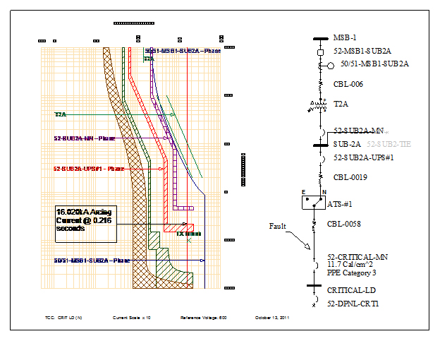
Figure 5
To model the ARMS device for the "52-SUB2A-UPS#1" component, we can create another function named "ARMS" for this device. We then assign this function the ARMS device from the static trip category of the protective device library. To activate this function in arc flash, make sure that the "Use in Arc Flash" check box is checked. See Figure 6.
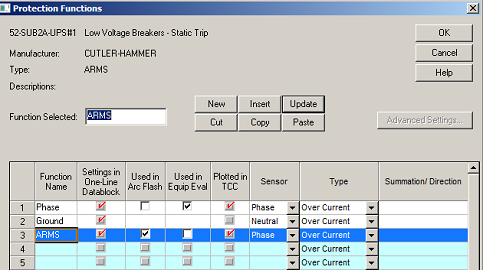
Figure 6
Once the ARMS device has been properly modeled and activated for arc flash study, the new result can be seen in Figure 7.
From Figure 7, we can see that if the fault happens on the line side "52-CRITICAL-MN", the arcing current of 16.02 kA going through, "52-SUB2A-UPS#1-ARMS" will now clear the fault at 0.05 seconds. This will produce a total incident energy of 2.8 cal/cm2.
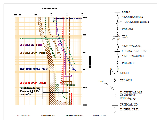
Figure 7
The next two figures illustrate how the multiple settings group (using DT 3000) works and modeled in the SKM software. Figure 8 shows a partial single line modeled in SKM software along with its corresponding time current curve (TCC). From the figure, we can see that if the fault happens on the line side "52-SUB3A-MN", the arcing current of 1.048 kA going through, "50/51-MSB1-SUB3A" will clear the fault at more than 2.0 seconds. This will produce a total incident energy of 49.7 cal/cm2.
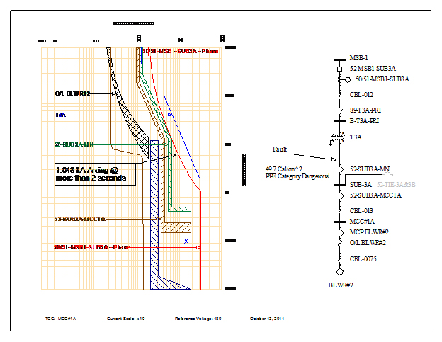
Figure 8
Multiple settings can be modeled in a similar fashion as the ARMS device mentioned above. This time we assign the new function the "DT 3000" from the relay category of the library. We then modify the setting of this new function such that the curve is an "L" shape curve. Once the multiple settings group has been properly modeled and activated for arc flash study, the new result can be seen in Figure 9.
From the Figure 9, we can see that if the fault happens on the line side "52-SUB3A-MN", the arcing current of 1.048 kA going through, "50/51-MSB1-SUB3A-DT 3000" will clear the fault at more than 0.2 seconds. This will produce a total incident energy of 7.4 cal/cm2.
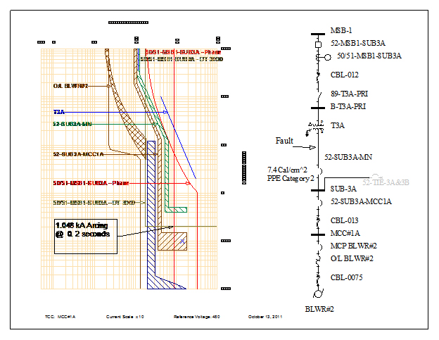
Figure 9
Other Arc Flash Instantaneous and Protection Schemes
Optical relay and Arc Vault are recent new technologies that had been developed to help with mitigating arc-flash incident energy. In a nutshell, these two devices clear or extinguish the arc flash in a matter of milliseconds when it is detected.
Optical relays works with light sensors that detect the sudden increase in light intensity. It also works with fault detector to prevent false tripping. When the optical sensor detects a sudden increase in light and the fault detector detects a fault, the optical relay sends a trip signal to the circuit breaker to trip in as fast as 2 milliseconds.
Arc Vault is a protection system that can be retrofitted with most low voltage switchgear, motor control centers, switchboard, etc. When this system detects an arc flash or spike in current, the containment dome is initiated to create a secondary arc to transfer and extinguish the original arc in the dome. The main breaker is also called upon trip to de-energize the system. All this happens is less than 8 milliseconds.
Also, alternative protection schemes (bus differential protection, zone interlocking, etc.) are gaining popularity, since these types of schemes clear the fault instantaneously.
For bus differential protection, the current going in and out of the bus are measured. If they are equal no action is taken. However, if the current are not equal, then the bus breakers are called upon to trip instantaneously.
Zone selective interlock (ZSI) is composed of a main breaker communicating with downstream breakers. In the event of a downstream fault, a signal is sent to the main breaker to hold, and the feeder breaker nearest the fault would trip. However, if a fault happens on the bus directly below the main breaker, the main breaker would be called upon to clear the fault instantaneously.
The protection schemes mentioned above do not really rely on a time over current device to clear an arc fault. The arc fault is cleared or extinguished instantaneously when certain criteria are met. To model this in SKM, the user could check the "Available" checkbox in the "Arc Flash Instantaneous Protection" in the "Equipment & Arc Flash" sub view of the said bus. See Figure 10. Once this is done, and the arc study has been re-run, the user can then enter his own trip delay time and breaker opening time. The incident energy is then recalculated based on the time that the user specified. See Figure 11.
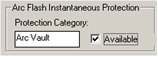
Figure 10
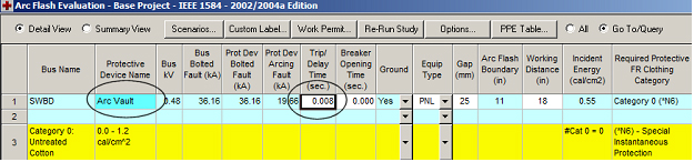
Figure 11
The next two figures show how using the arc flash Instantaneous works and modeled in the SKM software. Figure 12 shows a partial single line modeled in SKM software along with its corresponding time current curve (TCC). From this figure, we can see that if the fault happens on the "SWBD" bus, the arcing current of 17.11 kA going through, "SWDB MCB" will clear the fault at around 0.36 seconds. This will produce a total incident energy of 22.5 cal/cm2.
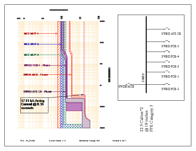
Figure 12
From the TCC, we can see that coordination is quite tight. To reduce the incident energy, changing the protective device settings may not be a feasible solution, since it may require redoing the coordination of the system. Let's assume that retrofitting the switchboard with an Arc Vault was selected to mitigate arc flash for this system.
Once the "Arc Flash Instantaneous Protection" has been properly modeled by following the steps above and setting the trip delay time to be 8 milliseconds, the new result can be seen in Figure 11 and 13.
From the Figure 11, we can see that if the arc flash happens on the "SWDB", the Arc Vault will extinguish it in 8 milliseconds (specified by the user). Based on this time, new total incident is now 0.55 cal/cm2.
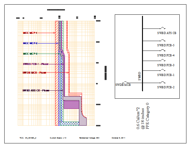
Figure 13
Conclusion
Arc flash is one of the most dangerous workplace hazards. Serious injuries and death could be cause by this hazard. One of the best and efficient ways to mitigate arc flash is to clear the arcing fault as fast as possible. There are various ways to achieve this. Modifying the existing settings of protective devices, applying new technologies such as ARMS and ARC Vault, and taking advantage of alternative protection schemes such as differential protection and zone interlocking, since these types of schemes clear the fault instantaneously, are some of the options available.
No one method works all the time. What works in one location may not work effectively in another location. The various arc flash mitigation techniques mentioned above was illustrated and modeled using the SKM Power*Tools for Windows software.