When and how to use two new powerful options in the Arc Flash module V7.0
In this paper, we will discuss the importance of becoming familiar with two new powerful options available for arc flash incident calculations in the SKM Arc Flash module V7.0.
As we can see in Figure 1, the Arc Flash Study Options (Report Options tab) screen, two options are shown: Main device fail to operate, use upstream devices and Use Maintenance Mode function for main device.
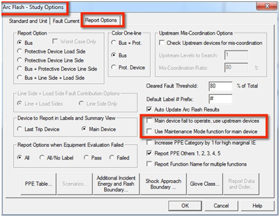
Figure 1
Each of these two new options has a specific use. We are going to explain and give examples of both options.
Option #1: Main device fail to operate, use upstream device
When any electrical equipment has a main overcurrent protection device - in contrast to main lugs only type equipment - there are two areas inside the equipment with different arc flash incident energies. They consist of the line-side incident energy area and the load-side incident energy area.
The line-side incident energy is present in the area upstream from the line-side terminals of the main overcurrent protection device, where the incoming conductors enter the equipment. This energy is not limited by the main overcurrent protection device but by the next upstream overcurrent protection device.
The load-side incident energy is present in the area downstream from the load-side terminals of the main overcurrent protection device. See Figure 2.
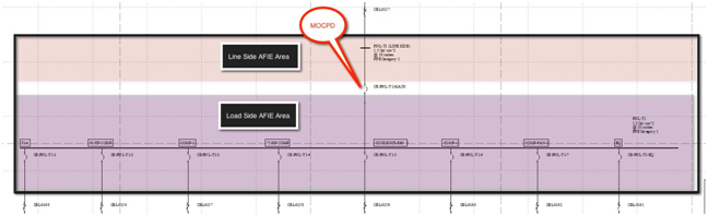
Figure 2
NOTE: The main overcurrent protection device is not always the overcurrent protection device that is connected to the incoming wires from the utility side. The main overcurrent protection device is defined in SKM as the overcurrent protection device that carries the biggest percentage of the fault current to the bus. In some very particular cases, a tiebreaker or even a feeder breaker might qualify as the main overcurrent protection device.
Normally, the line-side incident energy is higher than the load-side incident energy so it is advisable to calculate both.
There have been many articles written about the importance of calculating the incident energy at the line side of a main overcurrent protection device in addition to the load-side incident energy. One situation in the mind of many engineers is the following: What happens when the main overcurrent protection device fails to operate?
In this case, the upstream device from the main overcurrent protection device will be the one limiting the incident energy to the entire equipment. Now, instead of having two areas with different incident energy, (line-side and load-side incident energies), the electrical equipment has only the higher and worst case line-side incident energy. See Figure 3.
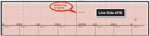
Figure 3
The preferred method to calculate the line-side incident energy (i.e. when the main overcurrent protection device fails to clear the arcing current) is to include a bus at the line-side of the main overcurrent protection device, as shown in Figure 2. However, this method will add many non-existent buses to the project database. If you have a software license with a limited number of buses, the database created using this method (of adding line-side non-existent buses) might easily exceed the number of buses allowed in your license. In this case, the option Main device failed to operate; use upstream device is very useful.
When you choose this option, at all locations where there is a main overcurrent protection device, the incident energy will be calculated assuming the following:
- The arc flash event occurred at the bus
- The main overcurrent protection device failed to operate, therefore it is ignored
- The first upstream overcurrent protection device from the main overcurrent protection device is the one that clears the arc flash event.
Figure 4 shows the arc flash table results for an arc flash event on location PNL-T1. The option Main device failed to operate; use upstream device has been checked and we have considered a maximum arcing time of 2 seconds.
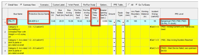
Figure 4
The location of the arc flash event (Bus Name) is shown as PNL-T1. The last tripped protective device is shown as CB-MDP-2-1, which is the upstream overcurrent protection device. The arc flash trip time (Trip/Delay Time) is shown as 2 seconds. Since the arc flash trip time of the upstream overcurrent protection device is 9 seconds - “ see Figure 5 - the Trip/Delay Time considers only up to the maximum arcing time of 2 seconds. And finally, on the PPE Level column, we can see code *N22 and the name of the main overcurrent protection device CB-PNL-T1-MAIN. The code *N22 is explained below as "Main Device failed, use upstream device". Figure 5 shows the time-current curve (TCC) for this situation.

Figure 5
Here we can visualize that the upstream overcurrent protection device is much slower to open the arcing current that the main overcurrent protection device. Without the option Main device failed to operate; use upstream device checked, the load-side incident energy (at location PNL-T1) would have been 1.1 cal/cm2 and the trip time of the main overcurrent protection device (CB-PNL-T1-MAIN) would have been of 0.028 seconds. But if you check this option, the main overcurrent protection device is ignored and the upstream overcurrent protection device (CB-MDP-2-1) is the one that clears the arcing current in 9 seconds. But since we have chosen a maximum arcing time of 2 seconds, the trip time of 9 seconds is changed to 2 seconds. This trip time gives a very high line-side trip time of 55 cal/cm2 that applies not only to the incoming section but also to the entire electrical equipment.
As previously discussed, you could decide to choose the option Main device failed to operate; use upstream device when you want to evaluate the incident energy when the main overcurrent protection device fails to operate. But there are additional justifications to choose this option. You might want to know the incident energy at the incoming section of the equipment to perform energized maintenance. Or the electrical panel has an open-frame construction and the incident energy at the incoming section (which corresponds to the line-side incident energy) might easily migrate to the adjacent feeder section where you are planning to work. Or it is the company policy to choose the worst case incident energy (normally the line-side incident energy) present in electrical equipment. Whatever your reason might be, the option Main device failed to operate; use upstream device allows you to calculate the line-side incident energy at any equipment, which has a main overcurrent protection device, easily and efficiently.
Option #2: Use Maintenance Mode function for Main Device
Arc flash incident energy mitigation is an important part of an arc flash hazard analysis. Once the incident energies are calculated, locations with high incident energies (normally ≥ 8 cal/cm2) could be identified.
The high incident energies identified at these locations, could be mitigated using many methods and technologies. The preferred method is to change the settings of existing circuit breakers so the arcing current will be cleared faster without any costly changes. But these setting changes could - and normally do - upset the coordination of the system making it more susceptible to partial or total blackouts. A new technology called "arc flash reduction maintenance system (ARMS)" allows a reasonable compromise between safety and continuity of service.
The ARMS device is normally a specialized circuit breaker with two independent functions. One function (normally named "phase") is selected when the system is in normal operation. The other function (normally assigned the named "ARMS") is activated ONLY when performing energized work on the protected equipment. Both functions (phase and ARMS) can't be active at the same time.
In the phase (normal) function, the settings of the ARMS device are chosen for protection and coordination of the electrical system during normal operations. In the ARMS (maintenance) function, the settings of the ARMS device are chosen to have a very fast response (no intentional delay) to the expected arcing current (not the available short circuit current). This fast response substantially diminishes the trip time and therefore the incident energy at the protected equipment.
The drawback for this gain in safety is the loss of coordination while the ARMS function is active.
It is important that the ARMS device should be located one level upstream from the equipment to be protected. For example, if the equipment to be protected is a power panel (with or without a main overcurrent protection device), the ARMS device should be installed in the upstream feeder panel. It is not recommended to install the ARMS device as the main overcurrent protection device at the protected power panel. See Figure 6.
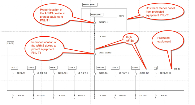
Figure 6
If the ARMS device is installed as the main overcurrent protection device, the load-side incident energy will be substantially reduced, but the more dangerous line-side AFIE will not be affected. In contrast, when the ARMS circuit breaker is installed in a separate enclosure, upstream from the equipment to be protected, the line-side and load-side incident energies are reduced.
To use the ARMS option in the Arc Flash module, you have to add an ARMS function to the circuit breaker to the already existing phase function. The scope of this article does not cover how to add this new function. We assume in this paper that the ARMS function already exists.
Since the ARMS device has two functions (each with its own settings), the Arc Flash module in SKM needs to know which of the two functions is active before running the study. To do so, you have two options.
First option: Enter the component editor of the ARMS device (a the Protective Device subview), then click on the Function button. This opens the Protection Functions screen. Now check the Use in Arc Flash check box corresponding to the ARMS function. Then click on the OK button. This will take you back to the Component Editor subview. Verify that the ARMS function name is shown to the left of the Toggle button. See sequence of Figure 7A and Figure 7B.
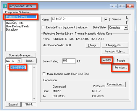
Figure 7A
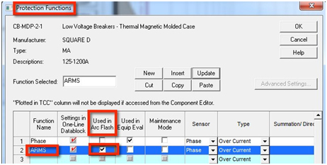
Figure 7B
Note that from this moment on, all arc flash calculations will be based on the ARMS function settings. If you want to calculate the incident energy using the normal phase function settings, it will be necessary to revert his procedure. This is a tedious process.
Second Option: Activate the Use Maintenance Mode function for Main Device. When this option is activated in the Arc Flash “ Study Options (Report Options tab) screen, the arc flash study will use the maintenance function settings if the checkbox Maintenance Mode in the Protection Function screen is checked for the ARMS device. See Figure 8. Therefore, when you create this ARMS function in your ARMS device, make sure that this checkbox is checked.
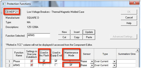
Figure 9
If you want to calculate the incident energies without the ARMS maintenance function settings active (i.e. calculate using the phase or normal settings), uncheck the Use Maintenance Mode function for Main Device check box from the Arc Flash “ Study Options screen on the Report Options tab. This procedure is much simpler than going to the Component Editor of the overcurrent protection device, then to the Protection Function screen and finally unchecking the Used in Arc Flash checkbox for the ARMS function and checking the Used in Arc Flash checkbox for the Phase function.